

Contents
- Mounting and Supporting the Insta360 X5/X4 Camera
- Point Cloud Colouring for MLS in TPP
- Practical Benefits for Professionals
The TOPODRONE team is developing an ecosystem of solutions for Mobile Laser Scanning (MLS), making specialists’ work more convenient and more efficient. The latest updates cover several areas at once: the enhancement of TOPODRONE LiDAR systems and the expansion of capabilities within the TOPODRONE Post Processing (TPP) software.
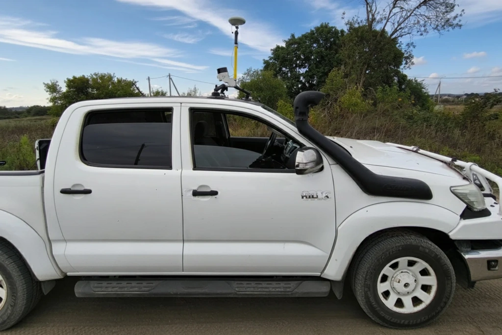
Figure 1. Vehicle-mounted MLS using SLAM with support for the Insta360 X4 camera
Vehicle Mount and Insta360 X5/X4 Camera Support
A specialised vehicle-mount has been developed to enable the use of TOPODRONE LiDAR 200+, 100+ and 100 scanners together with Insta360 X5 and X4 cameras. This solution expands the operational capabilities of the scanners, allowing large linear assets to be surveyed within very short timeframes.
The mounting bracket is compact (195×73×28 mm) and features two mounting holes: the upper hole is for a standard screw for a GNSS antenna, while the lower hole allows the camera to be attached to the bracket, which can then be fixed to a survey pole or vehicle mounting system.
Key features of the mounting kit:
- Camera installation without modification or replacement of standard MLS components;
- Support for various mounting scenarios: on a vehicle, survey pole, or other platforms using adapters and suction mounts;
- Retains standard scanner operation while simultaneously recording spherical video with the camera.
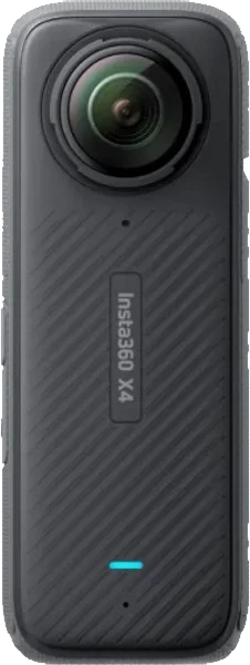
Figure 2. Insta360 X4 Camera
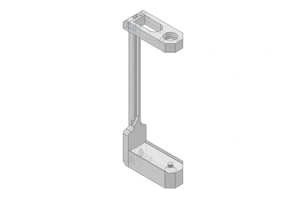
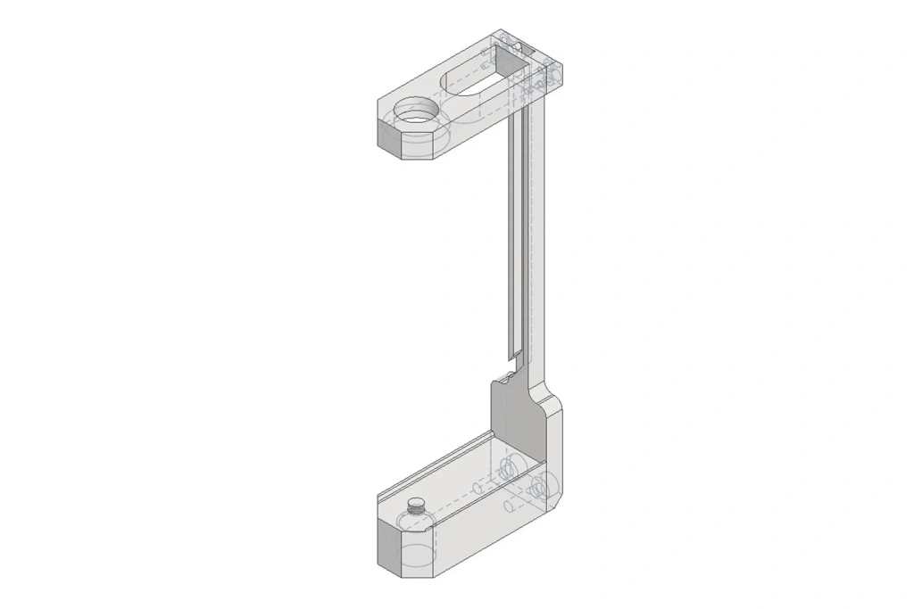
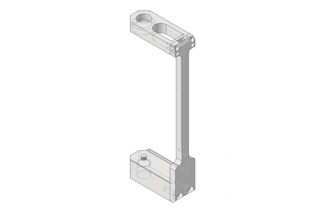
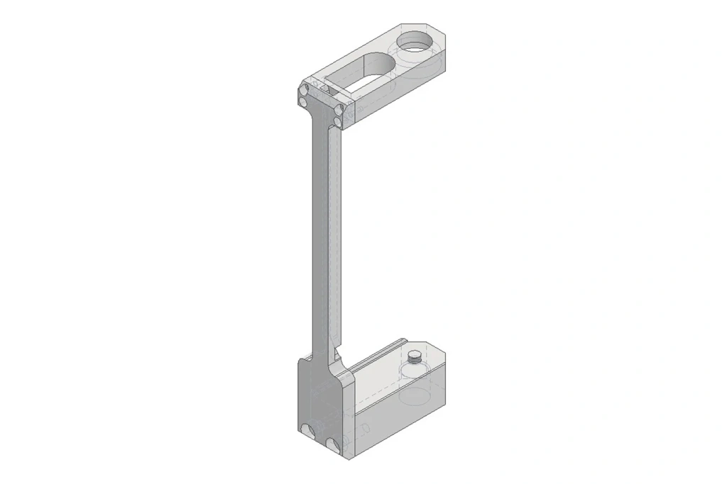
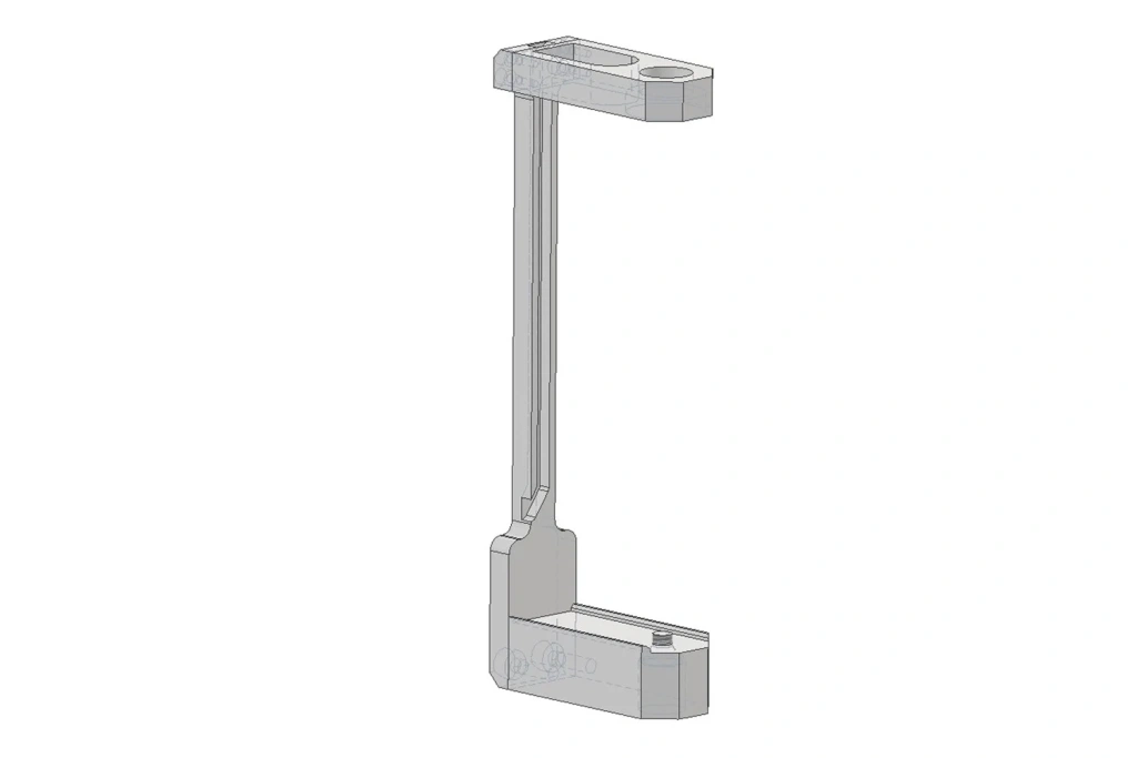
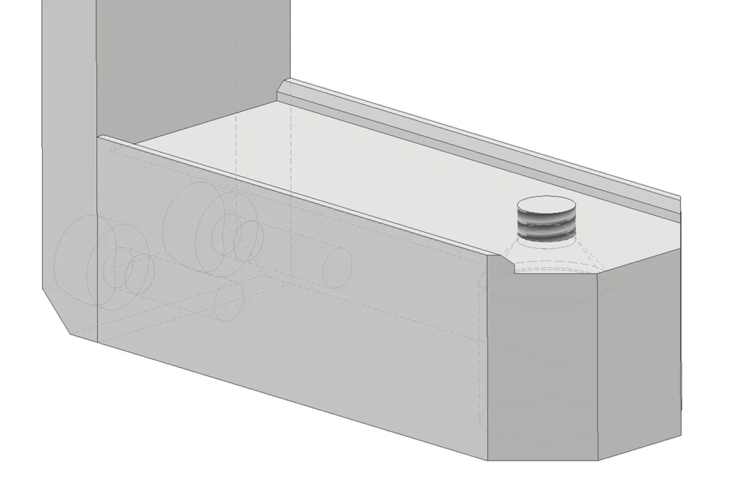
Figures 3–9. Camera Bracket
Mounting the Bracket
The bracket is easy to install and follows standard mounting procedures, with the difference that the bracket with the Insta360 X5/X4 camera is installed between the pole and the antenna. It is important to orient the camera so that the lens facing the display aligns with the scanner’s direction of movement. This ensures synchronized data capture, combining laser scanning with panoramic video recording.
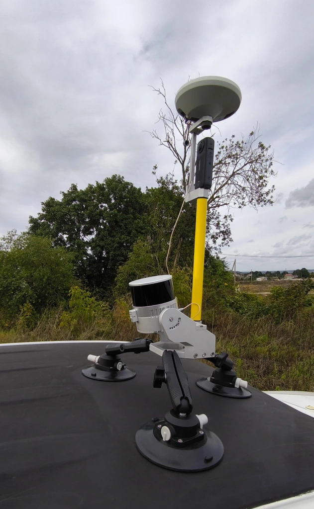
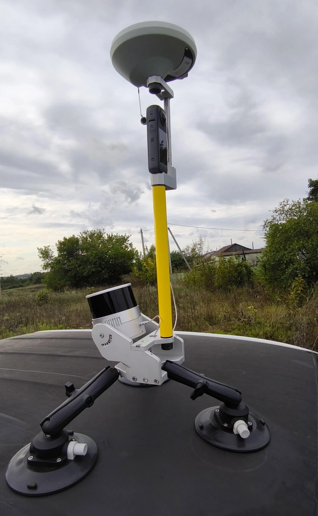
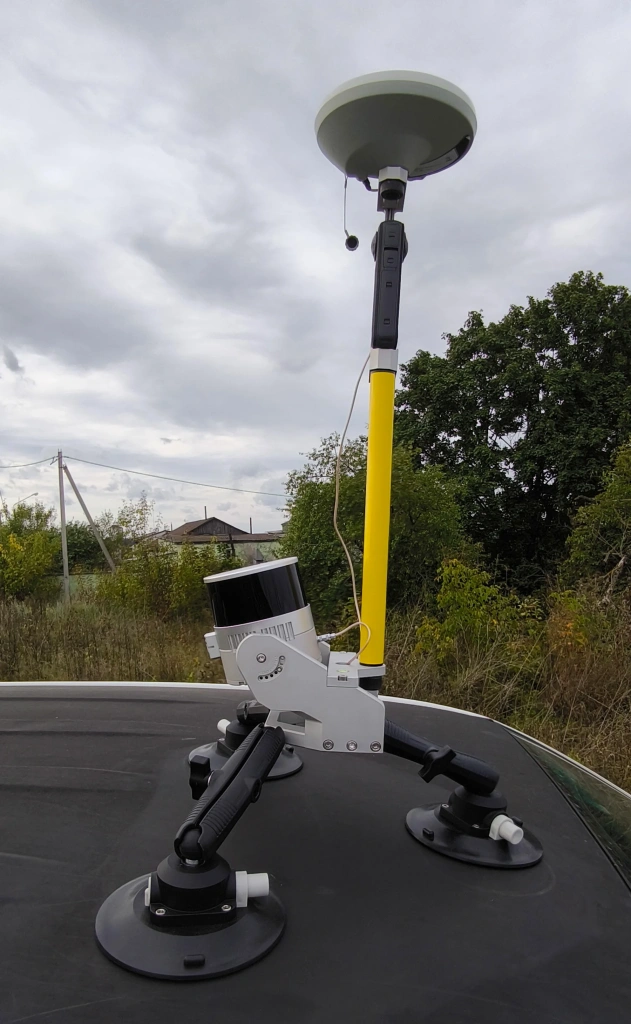
Figures 10–12. MLS kit with installed Insta360 X4
Video 1. Filming using the bracket with the Insta360 X4 camera
Point Cloud Colouring for MLS in TPP
TOPODRONE Post Processing now includes a point cloud colouring function for MLS data captured with TOPODRONE laser scanners. 3D models become not only geometrically accurate but also visually informative, simplifying quality control and analysis. This is particularly valuable for infrastructure, construction, and land monitoring projects.
Stages of the Colouring Process
The point cloud colouring process comprises three main stages:
- Determining the scanner trajectory. Using GNSS and inertial sensor data, the scanner’s actual path is calculated. A precise trajectory ensures correct positioning of each point and forms the basis for further processing.
- Determining calibration parameters. At this stage, angles and offsets between the scanner and the camera are calculated. Accurate calibration ensures all measurements align correctly within a single coordinate system.
- Generating the point cloud in the working coordinate system. After trajectory correction and calibration, a dense point cloud is generated. It is immediately transformed into the chosen coordinate system (national or local), eliminating the need for additional conversions and facilitating further work in CAD, BIM, and GIS environments.
Point Cloud Colouring
For the colouring process, a point cloud obtained during MLS is required. This cloud serves as the spatial foundation onto which colour information is applied.
Input data for colouring includes:
- Scanner trajectory file – contains the scanner’s path, allowing spatial coordinates to be matched with timestamps;
- Inertial measurement unit (IMU) data – records scanner orientation angles, ensuring accurate projection of images onto the point cloud;
- Insta360 X4 camera image catalogue – photographs provide the colour information applied to each point during processing.
Once all input data is prepared, the system performs:
- Automatic temporal synchronisation – matching images with point coordinates by timestamp;
- Spatial projection – applying colour information to each point.
The result is a coloured point cloud with assigned RGB values, ready for further analysis or visualisation.
Upon launch, TPP automatically:
- Temporally synchronises scanner and camera data;
- Projects image colours onto the point cloud, assigning each point an RGB value.
Video 2. TPP interface – example of point cloud colouring
Practical Benefits for Professionals
Visual Data Verification
Coloured point clouds allow specialists to quickly assess data quality and immediately identify gaps or defects. Colour overlay makes it easy to pinpoint areas requiring additional inspection or re-capture.
Time Savings
Automatic photo-to-point attachment eliminates manual work, significantly speeding up data processing and reducing errors that may occur during manual matching.
Flexibility of Use
The solution works across multiple mobile platforms: vehicles, ATVs, drones, or portable setups. The system’s versatility allows use in various conditions and projects without major adaptation.
Easy Integration
The camera and bracket can be easily added to existing equipment without modifications. The system is simple to install and does not require extensive operator training, enabling rapid expansion of existing MLS setups.