Topodrone DJI Mavic 2 Pro L1/L2 RTK/PPK

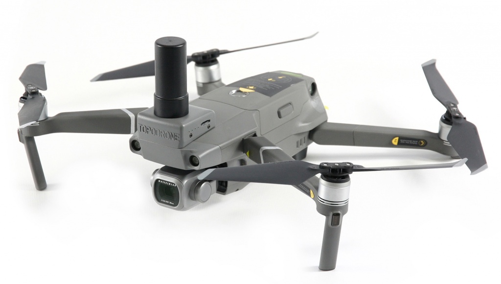
Img. 1. Topodrone DJI Mavic 2 Pro L1/L2 RTK/PPK.
Topodrone DJI Mavic 2 Pro L1/L2 RTK/PPK gains more and more popularity among the survey community.
This drone has the following advantages in comparison with other survey drones:
- Precise survey grade 186-channel L1/L2/L5 GNSS receiver synchronized with a 20Mp Hasselblad camera ;
- Small size and weight. It is the most compact survey drone on the market;
- Awesome flight capabilities and an advanced obstacle avoidance system;
- Usability and a wide range of mission-planning software.
To make things clear, we would like to talk about the aspects of a Rolling Shutter camera image processing, compare them to the Global Shutter cameras and demonstrate the ability of professional photogrammetric software Pix4Dmapper to compensate the distortion, caused by the Rolling Shutter effect.
Global and rolling camera shutters
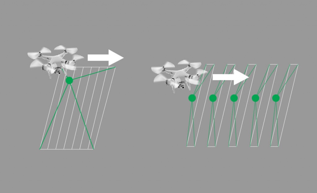
Take a look at the operation of the two main shutter types illustrated on the image.

Img. 2. Practical demonstration of global and rolling shutter operation.
Global shutter (on the left) takes a snapshot representing a single instant in time. This shutter type is common among the CCD sensor cameras.
Rolling shutter cameras (on the right) rapidly scan across the scene (from top to bottom) while taking a snapshot. The rolling shutter distortions usually appear when the position of an object in front of the camera changes during the line-by-line scanning of a single scene.

Img. 3. Practical demonstration the global shutter image acquisition and the rolling shutter line-by-line scene scanning.
If such distorted images are used with data processing software, the pixel displacement may cause problems while finding tie points on the images and thus become a reason of inaccurate internal and external image orientation parameters calculation.
Inaccurate camera parameters will surely cause the loss of orthophotomosaic and digital terrain model accuracy.
Compensation of the rolling shutter distortion in Pix4Dmapper software
Pix4Dmapper software uses a model for rolling shutter distortion compensation. This model corrects pixel displacement and thus calculates the parameters of internal and external image orientation.
The pixel displacement can be calculated with the following formula:
Δ ≈ V · T · f
P · h
here Δ - vertical pixel displacement,
V - drone speed (meters/sec),
T - time required by the sensor to scan the scene (seconds),
f - focal length (millimeters),
P (millimeters/pixel) - sensor pixel height,
h (meters) - flight altitude or distance between the sensor and an object.
The following concepts shall be distinguished:
- Readout time is the length of time when the light signal is converted to analog.
- Shutter Speed is the length of time when the digital sensor inside the camera is exposed to light.
The majority of data processing software is based on an assumption that the camera does not move while scanning the scene. The Pix4Dmapper rolling shutter distortion correction model takes into account the changes in camera position.
The camera position changes are approximated by applying a linear interpolation to two nearby camera positions (the beginning and the end of image scanning) for each series. Such linear approximation proved to be especially effective coupled with drones having a gimbal that stabilises the camera in nadir and with precise x,y,z coordinates of images.
The Pix4Dmapper rolling shutter correction feature allows performing flights at higher speeds without any decrease in final accuracy.
Processing survey data from Topodrone DJI Mavic 2 Pro L1/L2 RTK/PPK
To test the rolling shutter correction features we have carried out an aerial survey over the test area with the use of Topodrone DJI Mavic 2 Pro L1/L2 RTK/PPK equipped with a survey GNSS receiver that captures foto events with cm. level accuracy.
The flights have been performed by double grid mission with 80% overlapping, at the altitude of 90 and 120 meters and at the speed of 8 and 10 m/s respectively.

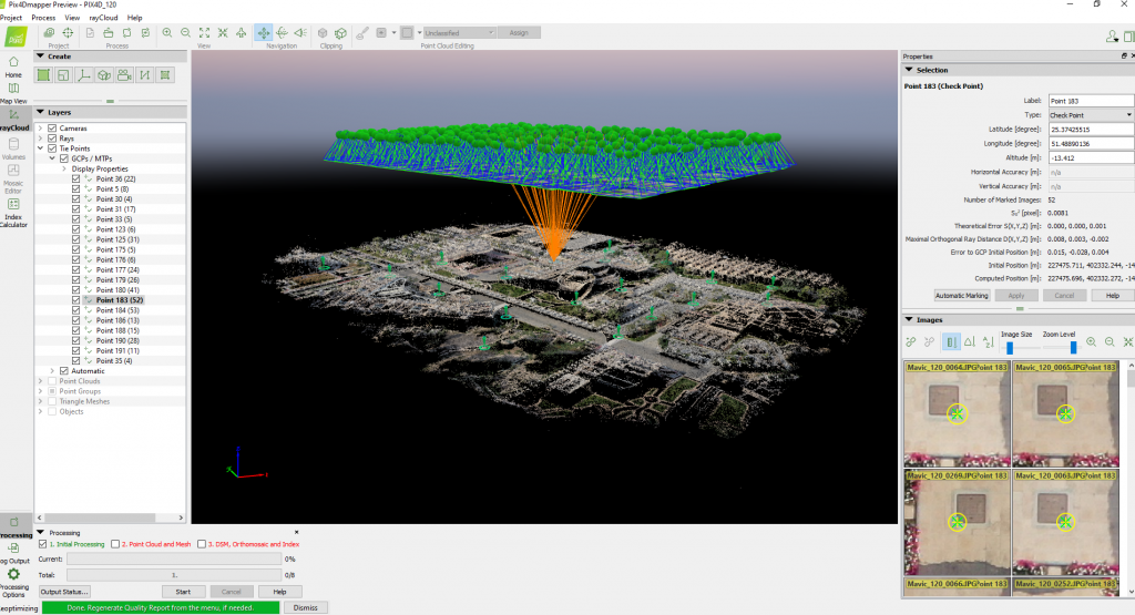
Img. 4. Photogrammetric processing with Pix4Dmapper software.
Photogrammetric processing was performed only with use of accurate images locations defined in PPK (post processing kinematic) mode. The only software used for automated GNSS data post processing and image geocoding was TOPOSETTER 2.0.
We measured evenly distributed among the whole working area ground check points (GCP) to estimate accuracy of aerial survey.

Img. 5. The aerial survey routes and ground control points.
Table1 and Table2 show the geolocation accuracy report of images collected at the altitude of 90 and 120 meters during double grid mission.
Table3 contains the results of single-route flight data processing quality control at the altitude of 120 meters.

Table 1. Data processing quality control report on the flight at 90 meters altitude.

Table 2. Data processing quality control report on the flight at 120 meters altitude.

Table 3. Single-route flight data processing quality control report at the altitude of 120 meters.
The scheme below clearly shows the sensor displacement vectors during the image-taking process and calculated values of camera speed, mean displacement and readout time values as well.

Img. 6. The scheme of image displacement and arrangement during the image-taking process.
Notably, the processing of data from the single grid mission 120-meters altitude flight showed the increase of errors at the ground check points located outside survey route border, where there is the lack of images overlapping.

Img. 7. The single flight route and ground control points position.

Img. 8. The position of ground control points with poor results.
Project results
The precision of the aerial model made with the use of double grid mission remains stable on the entire area of the survey.
As shown in tables above, x,y,z accuracy assessment of 3D model within the route borders fully meet the requirements of the 1:500 scale maps both in plane and in height.


Img. 9-11. Detailed point cloud, representing buildings and facilities, fencing, flora, road signs.
The project details are available at Pix4D Cloud, or you can download the whole data set and processing reports here.
Conclusion
The performed aerial survey proved high precision of the algorithms used in Pix4Dmapper software for rolling shutter distortion correction on practice.
Precise and highly detailed point cloud created with the data from Topodrone DJI Mavic 2 Pro L1/L2 RTK/PPK allows to digitize roads, buildings, walls, electricity lines, poles, vegetation etc in the office, substantially cutting number of field works and reducing the time and cost of survey projects significantly.
To conclude, this methodology of Topodrone DJI Mavic 2 Pro L1/L2 RTK/PPK aerial data processing has been fully tested by Pix4D (Switzerland) specialists. It has been recommended to provide all Topodrone DJI Mavic 2 Pro L1/L2 RTK/PPK users with this methodology of work.
The article was created using the materials published by Pix4D company.
