

Survey and reconstruction projects for road infrastructure demand high accuracy, operational efficiency, and maximum safety. Traditional surveying methods on busy roads pose risks to personnel and are time-constrained, even when partial traffic closures are applied.
Mobile laser scanning technology based on SLAM allows equipment to be mounted on a variety of platforms and enables surveying even in the absence of satellite signals.
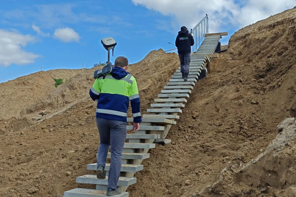
As part of one project, the TOPODRONE team scanned a 3.5 km² road interchange using the handheld SLAM 100 laser scanner. Fieldwork took just one hour, with achieved data accuracy of 3–5 cm.
The results enabled calculations of earthwork volumes and assessment of road surface conditions, overpasses, embankments, and adjacent mounds.
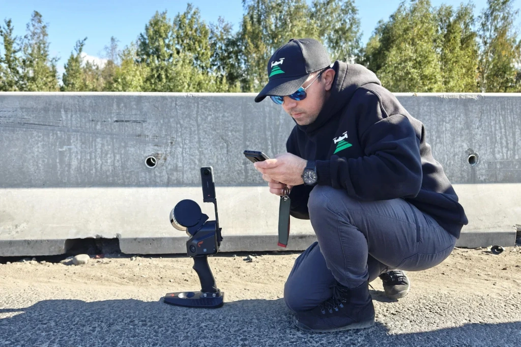
Figure 1. Road scanning with SLAM 100
Project objectives and specifics
The primary goal was to obtain a detailed point cloud and an orthophoto. These datasets allow an objective evaluation of the current state of the road interchange and can serve as a basis for preparing a feasibility study and developing a BIM reconstruction project.
The collected data enables:
- Vectorisation for generating topographic plans at any scale;
- Monitoring construction progress;
- Controlling contractor activities.
Site characteristics
GNSS signal limitations: The interchange passes through wooded areas and under an overpass, where satellite signals are unstable or absent. Additionally, signal interference from environmental factors may occur. SLAM operates autonomously and does not depend on GNSS.
Safety: Unlike total stations or terrestrial laser scanners, the technology does not require accessing live traffic lanes.
Operational efficiency: Minimal fieldwork time reduces impact on road traffic.
Detail: All infrastructure elements are captured: road surface, overpasses, embankments, terrain, and adjacent areas.
Why SLAM 100 was chosen
GNSS independence: Under the overpass, satellite signals are absent, yet the scanner remains stable.
High accuracy: Horizontal and vertical accuracy of 3–5 cm is suitable for engineering calculations.
Targeted scanning: Ability to locally supplement data without rescanning the entire site.
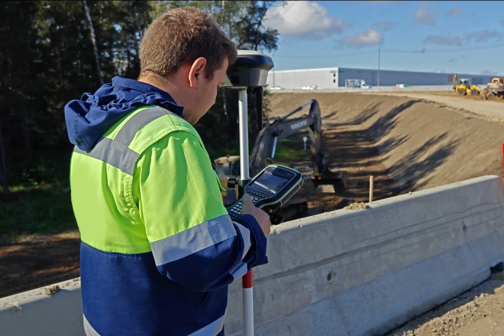
Mobility: Lightweight and compact scanner can be mounted on a vehicle, carried in a backpack, or operated handheld.
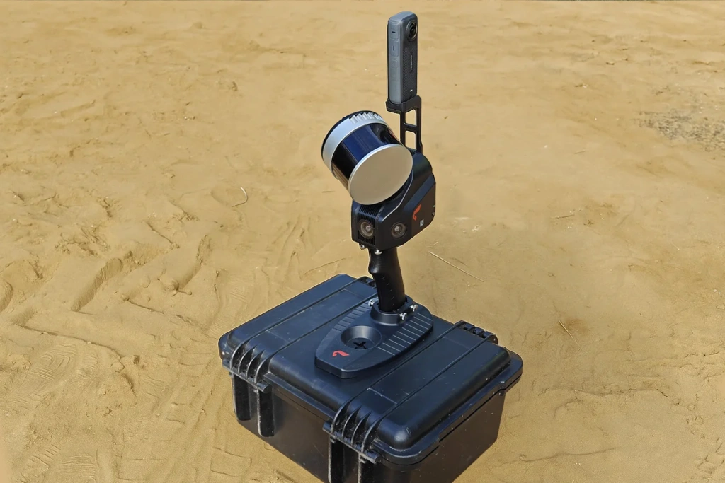
Figure 2. Mobile SLAM 100 laser scanner
Survey methodology
Preparatory stage
Before deployment, the following preparatory steps were undertaken:
Route planning: Based on mapping data, an optimal route was designed to ensure full coverage of the survey area with necessary overlaps in critical zones under the overpass.
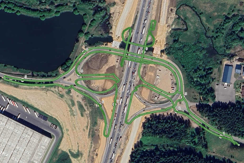
Figure 3. SLAM 100 survey route for road interchange
Equipment preparation: Batteries were charged, scanner functionality was checked, and the mobile device with the SLAM GO app was verified for real-time monitoring of the survey process.
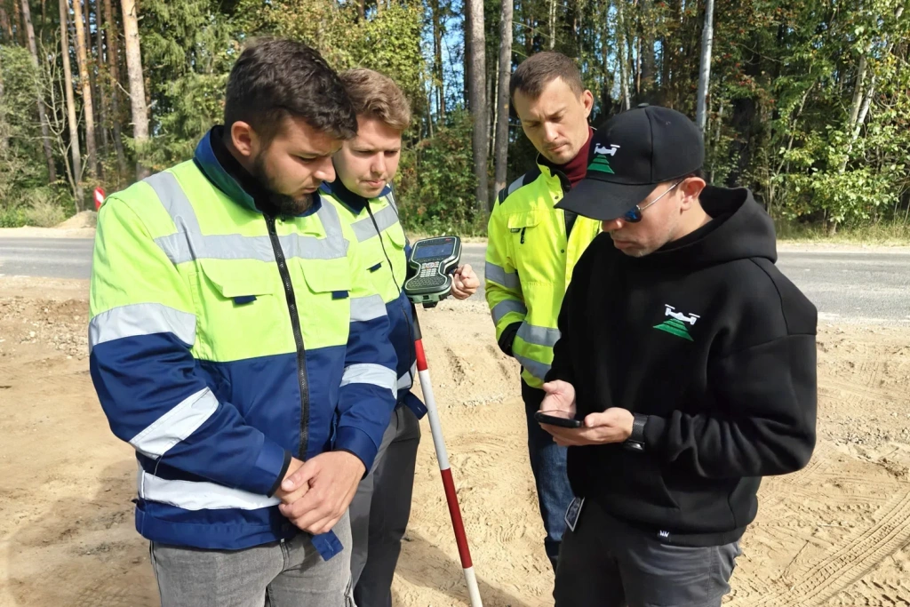
Figures 4–5. Preparatory stage
Fieldwork stage
The operator, using the handheld SLAM 100 scanner, followed the planned route spanning approximately 3.5 km, covering the entire interchange area.
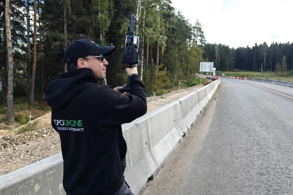
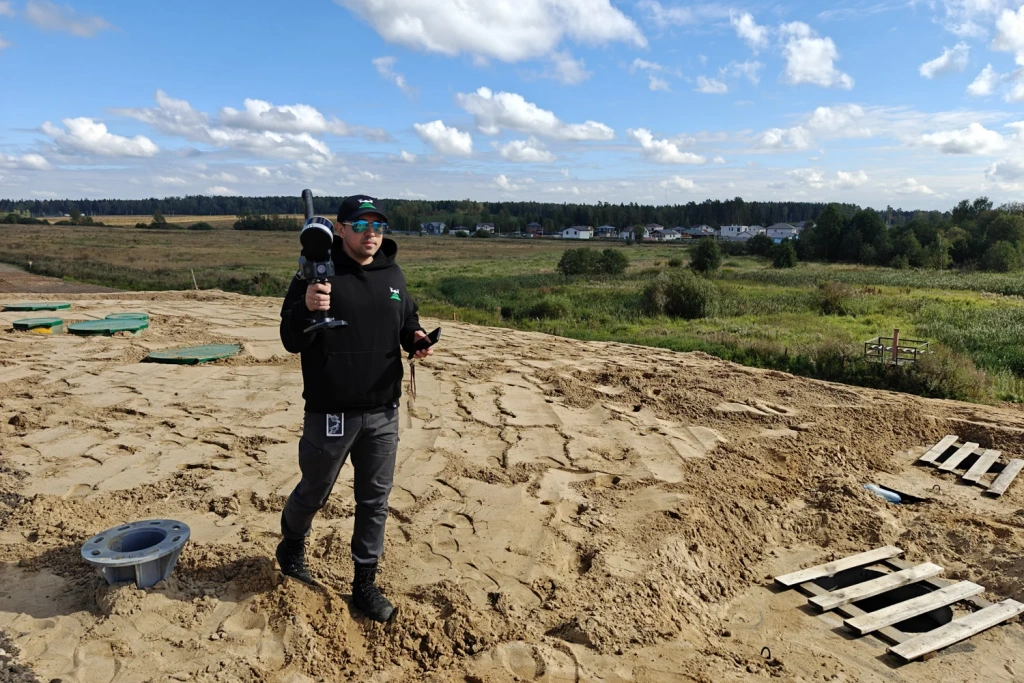
Figures 6–7. Fieldwork stage
In the section under the overpass, where GNSS signals were limited, the scanner maintained stable operation. Data quality was ensured through overlapping routes and point cloud density control.
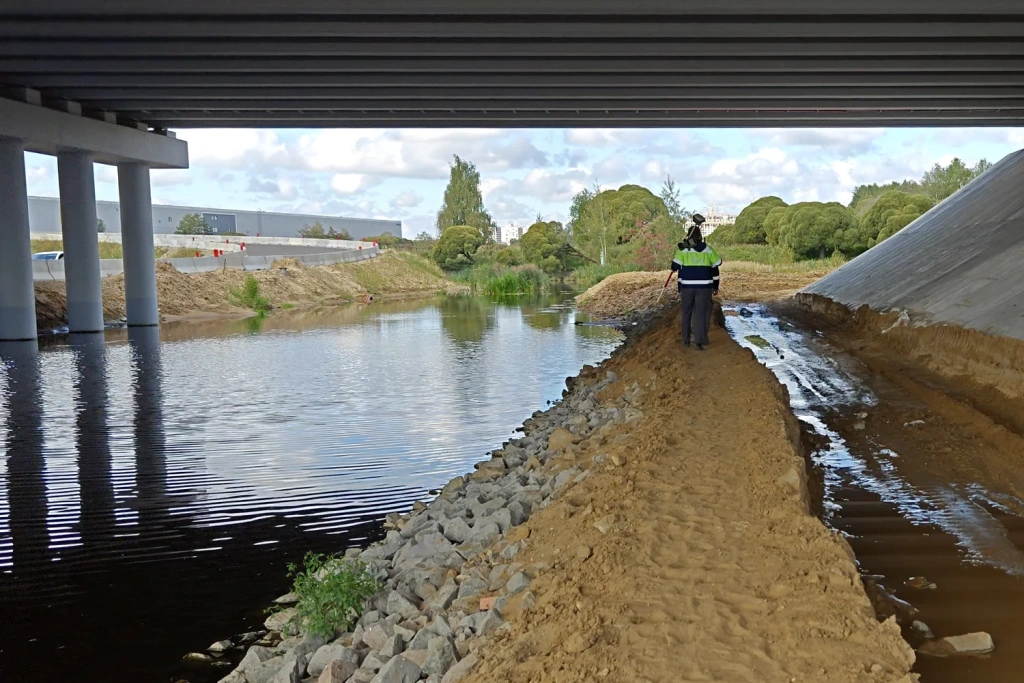
Figures 8–9. Overpass scanning
Using the SLAM GO app, the operator monitored the scanned area in real time and could immediately address any missing sections. Net scanning time was one hour.
Results and accuracy assessment
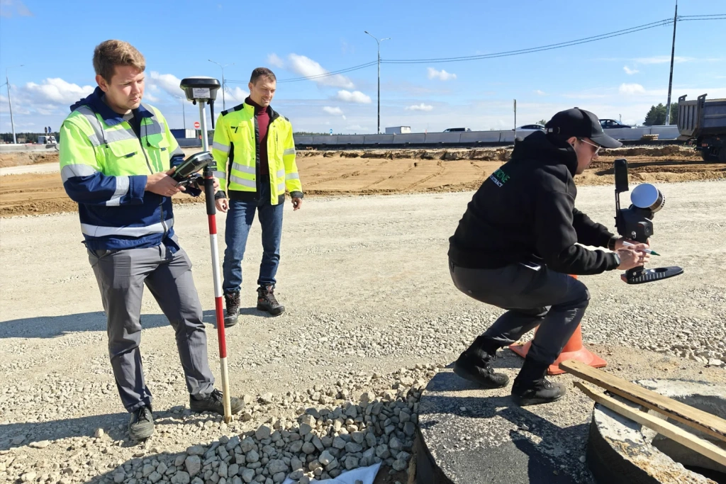
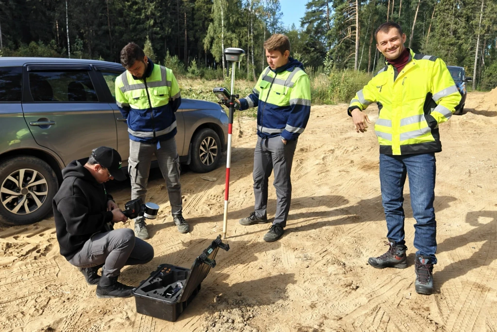
Figures 10–11. Accuracy assessment using GNSS receiver
Upon completion, the client received a comprehensive dataset ready for CAD/GIS import:
- Point cloud in LAS/LAZ format;
- Orthophoto.
Overpass survey
The overpass point cloud, with 3–5 cm accuracy, provides an initial understanding of structural condition, allows visual evaluation of key elements, and supports further engineering surveys or design work.
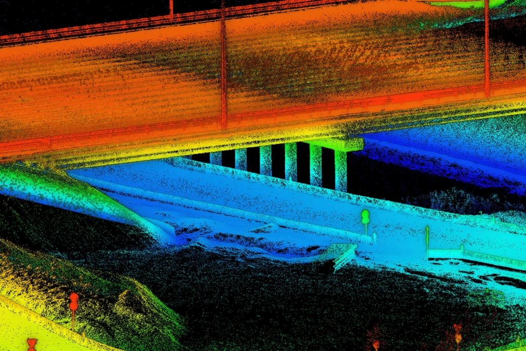
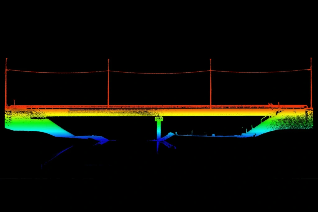
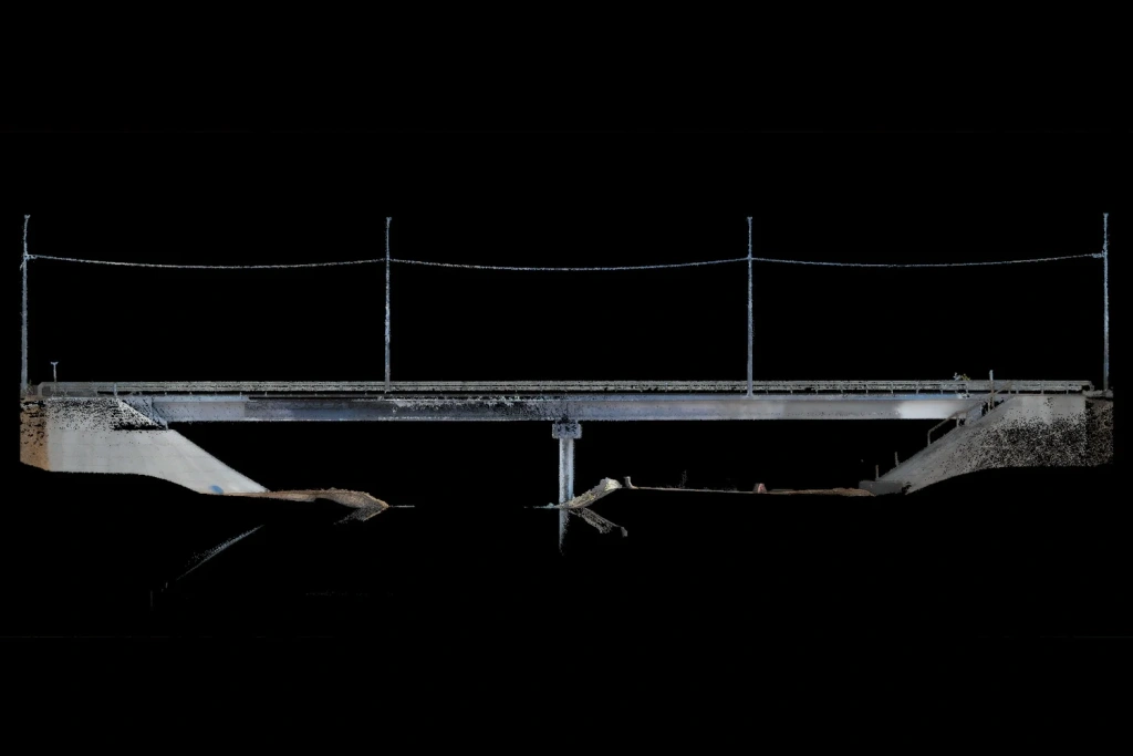
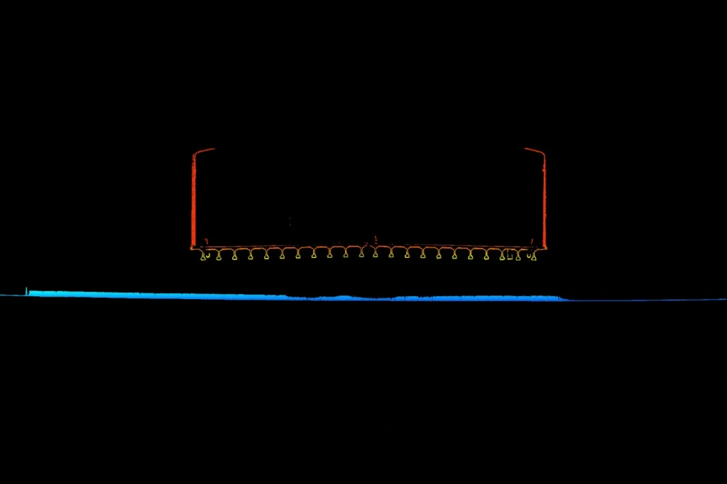

Figures 12–17. Overpass point clouds
Accuracy assessment
Control points measured with a total station were used for accuracy verification. Results showed an average error of 3–5 cm, fully meeting the project’s accuracy requirements for engineering purposes.
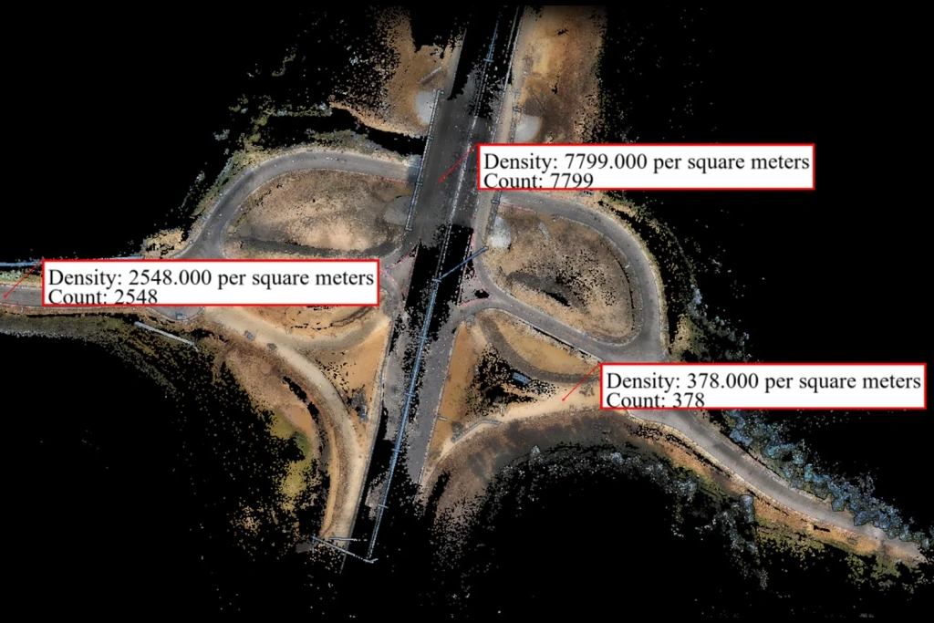
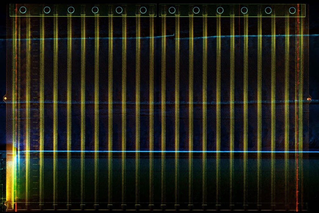
Figure 18. Detailed point cloud of road infrastructure
Accuracy table:
| X (m) | Y (m) | Known Z (m) | SLAM Z (m) | ΔZ (m) |
|---|---|---|---|---|
| 2213610.057 | 500653.445 | 158.186 | 158.1726 | -0.0134 |
| 2213496.893 | 500717.308 | 161.866 | 161.8362 | -0.0298 |
| 2213513.189 | 500753.897 | 161.458 | 161.5386 | 0.0806 |
| 2213260.745 | 500867.309 | 159.193 | 159.1922 | -0.0008 |
| 2213104.769 | 500797.442 | 158.747 | 158.8336 | 0.0866 |
| 2213301.282 | 500733.349 | 163.050 | 163.0159 | -0.0341 |
| 2213339.095 | 500735.088 | 164.282 | 164.2922 | 0.0102 |
| 2213248.197 | 500811.455 | 161.439 | 161.3582 | -0.0808 |
| 2213413.068 | 500868.361 | 163.502 | 163.5259 | 0.0239 |
Column explanation:
- X, Y (m) — control point coordinates in the local system
- Known Z (m) — elevation measured by GNSS receiver (RTK or standard GNSS)
- SLAM Z (m) — height determined from SLAM 100 data
- ΔZ (m) — difference between reference and scanned value (error)
Additional accuracy analysis (SLAM Orientation Accuracy Report):
- Relative accuracy: average deviation between distances — 1.7 cm, RMSE — 2.0 cm, confirming internal point cloud consistency.
Control using GCPs:
- Average deviation — up to 2 cm in plan (XY), no more than 3 mm in height (Z)
- RMSE: 1.3 cm in X, 1.5 cm in Y, 0.3 cm in Z
The data obtained provides accuracy sufficient for engineering calculations, including assessment of road surface condition, earthwork volume calculations, and BIM integration.
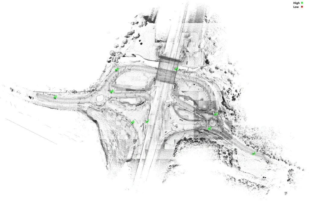
Figure 19. Orthophoto and accuracy assessment
Conclusion
Video 1. Overview of SLAM scanning
The project clearly demonstrated the efficiency of handheld SLAM 100 laser scanning for surveying road infrastructure.
- Speed: 3.5 km² area scanned in 1 hour
- Accuracy: 3–5 cm for engineering calculations
- Safety: work conducted without halting traffic or endangering personnel
- Versatility: stable operation in the absence of GNSS signal
Integration of the collected data into BIM will enhance design accuracy, accelerate engineering decisions, and reduce costs throughout the asset lifecycle.